High/Low Voltage Detection and Protection Circuit using PIC Microcontroller
EMBEDDED
High and Low Voltage Power Detector Circuit with Message Alert using PIC Microcontroller
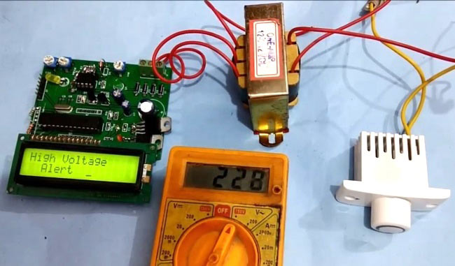
We often see voltage fluctuations in electricity supply at our home, which may cause malfunction in our home AC appliances. Today we are building a low cost High and Low Voltage Protection Circuit, which will cut off the power supply to the appliances in case of High or Low voltage. It will also show a alert message on 16x2 LCD. In this project, we have used PIC Microcontroller to read and compare the input voltage to the reference voltage and take the action accordingly.
We have made this circuit on PCB and added a additional circuit on PCB for the same purpose, but this time using op-amp LM358 (without microcontroller). For demonstration purpose, we have chosen Low Voltage limit as 150v and high voltage limit as 200v. Here in this project, we haven’t used any relay for cut off, we just demonstrated it using LCD, check the Video at the end of this Article. But the user may attach a relay with this circuit and connect it with PIC’s GPIO.
Further check our other PCB projects here.
Components Required:
- PIC Microcontroller PIC18F2520
- PCB (ordered from EasyEDA)
- IC LM358
- 3 pin Terminal Connector (optional)
- 16x2 LCD
- BC547 Transistor
- 1k resistor
- 2k2 resistor
- 30K resistor SMD
- 10k SMD
- Capacitors- 0.1uf, 10uF, 1000uF
- 28 pin IC base
- Male/female burgsticks
- 7805 Voltage regulators- 7805, 7812
- Pickit2 Programmer
- LED
- Zener diode- 5.1v, 7.5v, 9.2v
- Transformer 12-0-12
- 12MHz Crystal
- 33pF capacitor
- Voltage regulator(fan speed regulator)
Working Explanation:
In this High and Low Voltage Cut Off Circuit, we have read the AC voltage by using PIC microcontroller with the help of transformer, bridge rectifier & voltage divider circuit and displayed over 16x2 LCD. Then we have compared the AC voltage with the predefined limits and displayed the alert message over the LCD accordingly. Like if voltage is below 150v then we have shown “Low Voltage” and if voltage is above 200v then we have shown “High Voltage” text over the LCD. We can change those limits in PIC code given at the end of this project. Here we have used Fan Regulator to increase and decrease the incoming voltage for demonstration purpose in the Video.
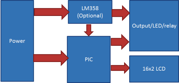
In this circuit, we have also added a Simple Under and Over Voltage Protection Circuit without using any microcontroller. In this simple circuit we have used LM358 comparator to compare the input and reference voltage. So here we have three options in this project:
- Measure and compare the AC voltage with the help of transformer, bridge rectifier, voltage divider circuit and PIC microcontroller.
- Detection of over and under voltage by using LM358 with the help of transformer, rectifier, and comparator LM358 (without Microcontroller)
- Detect under and over voltage by using a comparator LM358 and feed its output to PIC microcontroller for taking action by code.
Here we have demonstrated first option of this project. In which we have stepped down AC input voltage and then converted that into DC by using a bridge rectifier and then again mapped this DC voltage to 5v and then finally fed this voltage to PIC microcontroller for comparison and display.
In PIC microcontroller we have read this mapped DC voltage and based on that mapped value we have calculated the incoming AC voltage with the help of given formula:
volt= ((adcValue*240)/1023)
where adcValue is equivalent DC input voltage value at PIC controller ADC pin and volt is the applied AC voltage. Here we have taken 240v as maximum input voltage.
or alternatively we can use given method for mapping equivalent DC input value.
volt = map(adcVlaue, 530, 895, 100, 240)
where adcValue is equivalent DC input voltage value at PIC controller ADC pin, 530 is minimum DC voltage equivalent and 895 is maximum DC voltage equivalent value. And 100v is minimum mapping voltage and 240v is maximum mapping voltage.
Means 10mV DC input at PIC ADC pin is equal to 2.046 ADC equivalent value. So here we have selected 530 as minimum value means, the voltage at PIC’s ADC pin will be:
(((530/2.046)*10)/1000) Volt
2.6v which will be mapped minimum value of 100VAC
(Same calculation for maximum limit).
Check the map function is given in the PIC program code in the end. Learn more about Voltage Divider Circuit and mapping the Voltages using ADC here.
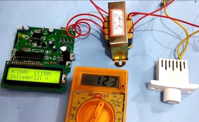
Working of this project is easy. In this project, we have used an AC voltage fan regulator for demonstrating it. We have attached fan regulator to the input of transformer. And then by increasing or decreasing its resistance we got desired voltage output.
In the code, we have fixed maximum and minimum voltage values for High voltage and Low voltage detection. We have fixed 200v as overvoltage limit and 150v as lower voltage limit. Now after powering up the circuit, we can see the AC input voltage over the LCD. When input voltage increases then we can see voltage changes over LCD and if voltage becomes more than over voltage limit then LCD will alert us by “HIGH Voltage Alert” and if the voltage goes low than under voltage limit then LCD will alert us by showing “LOW Voltage Alert” message. This way it can be also used as Electronic Circuit breaker.
We can further add a relay to attach any AC appliances to auto cutoff on low or high voltages. We just need to add a line of code to switch off the appliance, below the LCD alert message showing code. Check here to use Relay with AC appliances.
Circuit Explanation:
In High and low Voltage Protection Circuit, we have used an LM358 op-amp which has two outputs connected to 2 and 3 number pins of PIC microcontroller. And a voltage divider is used to divide voltage and connects its output at 4th number pin of PIC microcontroller. LCD is connected at PORTB of the PIC in 4-bit mode. RS and EN are directly connected at B0 and B1 and data pins D4, D5, D6 and D7of LCD are connected at B2, B3, B4 and B5 respectively. In this project, we have used two voltage regulator: 7805 for microcontroller supply and 7812 for the LM358 circuit. And a 12v-0-12v step-down transformer is also used to step down the AC voltage. Rest of the components are shown in the circuit diagram below.

Programming Explanation:
Programming part of this project is easy. In this code, we just need to calculate AC voltage by using mapped 0-5v voltage coming from Voltage Divider Circuit and then compare it with predefined values. You can check the complete PIC code after this project.
First, in the code, we have included a header and configured the PIC microcontroller config bits. If you are new to PIC coding then learn PIC Microcontroller and its configuration bits here.
Then we have used some fucntions for driving LCD, like void lcdbegin() for initializing the LCD, void lcdcmd(char ch) for sending a command to LCD, void lcdwrite(char ch) for sending data to LCD and void lcdprint(char *str) for sending string to LCD. Check all the functions in the code below.
Below given function is used for mapping the values:
long map(long x, long in_min, long in_max, long out_min, long out_max)
{
  return (x - in_min) * (out_max - out_min) / (in_max - in_min) + out_min;
}
Given int analogRead(int ch) function is used for initializing and reading ADC:
int analogRead(int ch)
{
    int adcData=0;
    if(ch == 0)
    ADCON0 = 0x03;       // adc channel 0
    else if(ch == 1)
    ADCON0 = 0x0b;       //select adc channel 1
    else if(ch == 2)
    ADCON0 = 0x0b;        //select adc channel 2
    ADCON1 = 0b00001100;     // select analog i/p     0,1 and 2 channel of ADC
    ADCON2 = 0b10001010;    //eqisation time holding cap time
    while(GODONE==1);       // start conversion adc value
    adcData = (ADRESL)+(ADRESH<<8);     //Store 10-bit output
    ADON=0;            // adc off
    return adcData;
}
Given lines are used for getting ADC samples and calculate average of them and then calculating voltage:
while(1)
{
    long adcValue=0;
    int volt=0;
    for(int i=0;i<100;i++)   // taking samples
    {
        adcValue+=analogRead(2);
        delay(1);
    }
    adcValue/=100;

    #if method == 1
    volt= (((float)adcValue*240.0)/1023.0);
    #else
    volt = map(adcValue, 530, 895, 100, 240);
    #endif
    sprintf(result,"%d",volt);
And finally given function is used for taking resulted action:
    if(volt > 200)
    {
        lcdcmd(1);
        lcdprint("High Voltage");
        lcdcmd(192);
        lcdprint("  Alert  ");
        delay(1000);
    }

    else if(volt < 150)
    {
        lcdcmd(1);
        lcdprint("Low Voltage");
        lcdcmd(192);
        lcdprint("  Alert  ");
        delay(1000);
    }
Circuit and PCB Design using EasyEDA:
To design this HIGH and LOW Voltage Detector Circuit, we have chosen the online EDA tool called EasyEDA. We have previously used EasyEDA many times and found it very convenient to use compared to other PCB fabricators. Check here our all the PCB projects. EasyEDA is not only the one stop solution for schematic capture, circuit simulation and PCB design, they also offer a low cost PCB Prototype and Components Sourcing service. They recently launched their component sourcing service where they have a large stock of electronic components and users can order their required components along with the PCB order.
While designing your circuits and PCBs, you can also make your circuit and PCB designs public so that other users can copy or edit them and can take benefit from there, we have also made our whole Circuit and PCB layouts public for this High and Low Voltage Protection Circuit, check the below link:
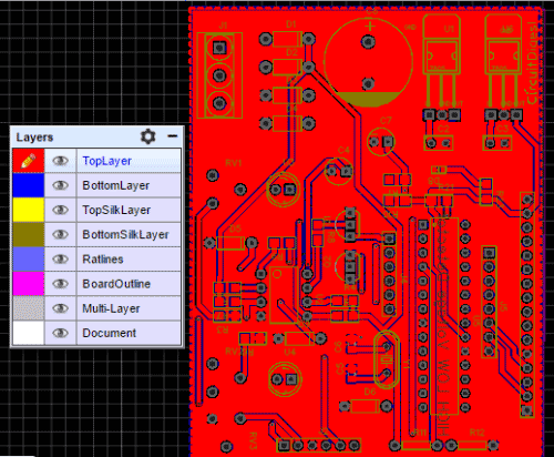
Below is the Snapshot of Top layer of PCB layout from EasyEDA, you can view any Layer (Top, Bottom, Topsilk, bottomsilk etc) of the PCB by selecting the layer form the ‘Layers’ Window.
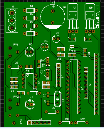
You can also checkout the Photo view of PCB using EasyEDA:
Calculating and Ordering PCBs online:
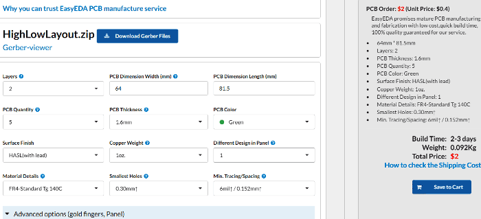
After completing the design of PCB, you can click the icon of Fabrication output above. Then you will access the page PCB order to download Gerber files of your PCB and send them to any manufacturer, it’s also a lot easier (and cheaper) to order it directly in EasyEDA. Here you can select the number of PCBs you want to order, how many copper layers you need, the PCB thickness, copper weight, and even the PCB color. After you have selected all of the options, click “Save to Cart” and complete your order, then you will get your PCBs a few days later. The user may also go with their local PCB vendor to make PCBs by using Gerber file.
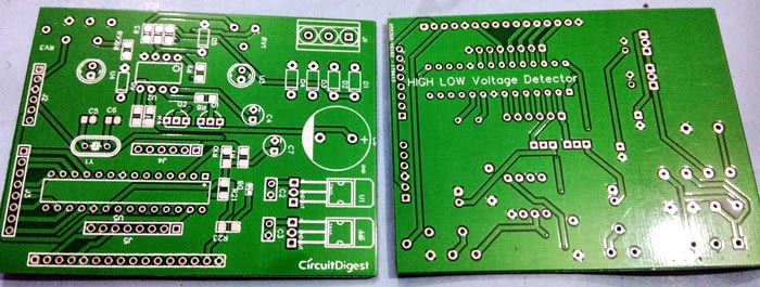
EasyEDA’s delivery is very fast and after few days of ordering PCB’s I got the PCB samples:
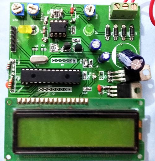
Below are the pictures after soldering the components on PCB:
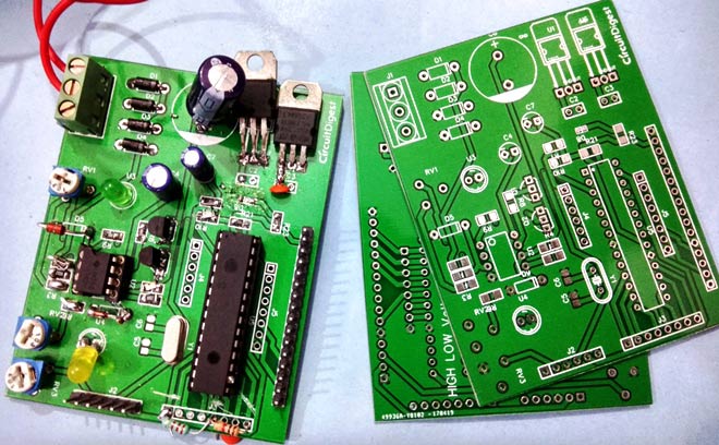
This how we can easily build the Low-high voltage protection circuit for our home. Further you just need to add a relay to connect any AC appliances to it, to protect it from voltage fluctuations. Just connect the relay with any general purpose Pin of PIC MCU and write the code to make that pin High and low along with LCD alert message code.
Code
#include<xc.h> //xc8 is compiler
#include<stdio.h>
#include<stdlib.h>
#include<stdio.h>
#include<stdlib.h>
// CONFIG1H
#pragma config OSC = HS // Oscillator Selection bits (HS oscillator)
#pragma config FCMEN = OFF // Fail-Safe Clock Monitor Enable bit (Fail-Safe Clock Monitor disabled)
#pragma config IESO = OFF // Internal/External Oscillator Switchover bit (Oscillator Switchover mode disabled)
#pragma config OSC = HS // Oscillator Selection bits (HS oscillator)
#pragma config FCMEN = OFF // Fail-Safe Clock Monitor Enable bit (Fail-Safe Clock Monitor disabled)
#pragma config IESO = OFF // Internal/External Oscillator Switchover bit (Oscillator Switchover mode disabled)
// CONFIG2L
#pragma config PWRT = ON // Power-up Timer Enable bit (PWRT disabled)
#pragma config BOREN = SBORDIS // Brown-out Reset Enable bits (Brown-out Reset enabled in hardware only (SBOREN is disabled))
#pragma config BORV = 3 // Brown Out Reset Voltage bits (Minimum setting)
#pragma config PWRT = ON // Power-up Timer Enable bit (PWRT disabled)
#pragma config BOREN = SBORDIS // Brown-out Reset Enable bits (Brown-out Reset enabled in hardware only (SBOREN is disabled))
#pragma config BORV = 3 // Brown Out Reset Voltage bits (Minimum setting)
// CONFIG2H
#pragma config WDT = OFF // Watchdog Timer Enable bit (WDT disabled (control is placed on the SWDTEN bit))
#pragma config WDTPS = 32768 // Watchdog Timer Postscale Select bits (1:32768)
#pragma config WDT = OFF // Watchdog Timer Enable bit (WDT disabled (control is placed on the SWDTEN bit))
#pragma config WDTPS = 32768 // Watchdog Timer Postscale Select bits (1:32768)
// CONFIG3H
#pragma config CCP2MX = PORTC // CCP2 MUX bit (CCP2 input/output is multiplexed with RB1)
#pragma config PBADEN = OFF // PORTB A/D Enable bit (PORTB<4:0> pins are configured as digital I/O on Reset)
#pragma config LPT1OSC = OFF // Low-Power Timer1 Oscillator Enable bit (Timer1 configured for higher power operation)
#pragma config MCLRE = ON // MCLR Pin Enable bit (MCLR pin enabled; RE3 input pin disabled)
#pragma config CCP2MX = PORTC // CCP2 MUX bit (CCP2 input/output is multiplexed with RB1)
#pragma config PBADEN = OFF // PORTB A/D Enable bit (PORTB<4:0> pins are configured as digital I/O on Reset)
#pragma config LPT1OSC = OFF // Low-Power Timer1 Oscillator Enable bit (Timer1 configured for higher power operation)
#pragma config MCLRE = ON // MCLR Pin Enable bit (MCLR pin enabled; RE3 input pin disabled)
// CONFIG4L
#pragma config STVREN = ON // Stack Full/Underflow Reset Enable bit (Stack full/underflow will cause Reset)
#pragma config LVP = OFF // Single-Supply ICSP Enable bit (Single-Supply ICSP disabled)
#pragma config XINST = OFF // Extended Instruction Set Enable bit (Instruction set extension and Indexed Addressing mode disabled (Legacy mode))
#pragma config STVREN = ON // Stack Full/Underflow Reset Enable bit (Stack full/underflow will cause Reset)
#pragma config LVP = OFF // Single-Supply ICSP Enable bit (Single-Supply ICSP disabled)
#pragma config XINST = OFF // Extended Instruction Set Enable bit (Instruction set extension and Indexed Addressing mode disabled (Legacy mode))
// CONFIG5L
#pragma config CP0 = OFF // Code Protection bit (Block 0 (000800-001FFFh) not code-protected)
#pragma config CP1 = OFF // Code Protection bit (Block 1 (002000-003FFFh) not code-protected)
#pragma config CP2 = OFF // Code Protection bit (Block 2 (004000-005FFFh) not code-protected)
#pragma config CP3 = OFF // Code Protection bit (Block 3 (006000-007FFFh) not code-protected)
#pragma config CP0 = OFF // Code Protection bit (Block 0 (000800-001FFFh) not code-protected)
#pragma config CP1 = OFF // Code Protection bit (Block 1 (002000-003FFFh) not code-protected)
#pragma config CP2 = OFF // Code Protection bit (Block 2 (004000-005FFFh) not code-protected)
#pragma config CP3 = OFF // Code Protection bit (Block 3 (006000-007FFFh) not code-protected)
// CONFIG5H
#pragma config CPB = OFF // Boot Block Code Protection bit (Boot block (000000-0007FFh) not code-protected)
#pragma config CPD = OFF // Data EEPROM Code Protection bit (Data EEPROM not code-protected)
#pragma config CPB = OFF // Boot Block Code Protection bit (Boot block (000000-0007FFh) not code-protected)
#pragma config CPD = OFF // Data EEPROM Code Protection bit (Data EEPROM not code-protected)
// CONFIG6L
#pragma config WRT0 = OFF // Write Protection bit (Block 0 (000800-001FFFh) not write-protected)
#pragma config WRT1 = OFF // Write Protection bit (Block 1 (002000-003FFFh) not write-protected)
#pragma config WRT2 = OFF // Write Protection bit (Block 2 (004000-005FFFh) not write-protected)
#pragma config WRT3 = OFF // Write Protection bit (Block 3 (006000-007FFFh) not write-protected)
#pragma config WRT0 = OFF // Write Protection bit (Block 0 (000800-001FFFh) not write-protected)
#pragma config WRT1 = OFF // Write Protection bit (Block 1 (002000-003FFFh) not write-protected)
#pragma config WRT2 = OFF // Write Protection bit (Block 2 (004000-005FFFh) not write-protected)
#pragma config WRT3 = OFF // Write Protection bit (Block 3 (006000-007FFFh) not write-protected)
// CONFIG6H
#pragma config WRTC = OFF // Configuration Register Write Protection bit (Configuration registers (300000-3000FFh) not write-protected)
#pragma config WRTB = OFF // Boot Block Write Protection bit (Boot block (000000-0007FFh) not write-protected)
#pragma config WRTD = OFF // Data EEPROM Write Protection bit (Data EEPROM not write-protected)
#pragma config WRTC = OFF // Configuration Register Write Protection bit (Configuration registers (300000-3000FFh) not write-protected)
#pragma config WRTB = OFF // Boot Block Write Protection bit (Boot block (000000-0007FFh) not write-protected)
#pragma config WRTD = OFF // Data EEPROM Write Protection bit (Data EEPROM not write-protected)
// CONFIG7L
#pragma config EBTR0 = OFF // Table Read Protection bit (Block 0 (000800-001FFFh) not protected from table reads executed in other blocks)
#pragma config EBTR1 = OFF // Table Read Protection bit (Block 1 (002000-003FFFh) not protected from table reads executed in other blocks)
#pragma config EBTR2 = OFF // Table Read Protection bit (Block 2 (004000-005FFFh) not protected from table reads executed in other blocks)
#pragma config EBTR3 = OFF // Table Read Protection bit (Block 3 (006000-007FFFh) not protected from table reads executed in other blocks)
#pragma config EBTR0 = OFF // Table Read Protection bit (Block 0 (000800-001FFFh) not protected from table reads executed in other blocks)
#pragma config EBTR1 = OFF // Table Read Protection bit (Block 1 (002000-003FFFh) not protected from table reads executed in other blocks)
#pragma config EBTR2 = OFF // Table Read Protection bit (Block 2 (004000-005FFFh) not protected from table reads executed in other blocks)
#pragma config EBTR3 = OFF // Table Read Protection bit (Block 3 (006000-007FFFh) not protected from table reads executed in other blocks)
// CONFIG7H
#pragma config EBTRB = OFF // Boot Block Table Read Protection bit (Boot block (000000-0007FFh) not protected from table reads executed in other blocks)
#pragma config EBTRB = OFF // Boot Block Table Read Protection bit (Boot block (000000-0007FFh) not protected from table reads executed in other blocks)
#define rs RB0
#define en RB1
char result[10];
#define lcdport PORTB
#define method 0
#define en RB1
char result[10];
#define lcdport PORTB
#define method 0
void delay(unsigned int Delay)
{
int i,j;
for(i=0;i<Delay;i++)
for(j=0;j<1000;j++);
}
{
int i,j;
for(i=0;i<Delay;i++)
for(j=0;j<1000;j++);
}
void lcdcmd(char ch)
{
lcdport= (ch>>2)& 0x3C;
rs=0;
en=1;
delay(1);
en=0;
lcdport= (ch<<2) & 0x3c;
rs=0;
en=1;
delay(1);
en=0;
}
{
lcdport= (ch>>2)& 0x3C;
rs=0;
en=1;
delay(1);
en=0;
lcdport= (ch<<2) & 0x3c;
rs=0;
en=1;
delay(1);
en=0;
}
void lcdwrite(char ch)
{
lcdport=(ch>>2) & 0x3c;
rs=1;
en=1;
delay(1);
en=0;
lcdport=(ch<<2) & 0x3c;
rs=1;
en=1;
delay(1);
en=0;
}
{
lcdport=(ch>>2) & 0x3c;
rs=1;
en=1;
delay(1);
en=0;
lcdport=(ch<<2) & 0x3c;
rs=1;
en=1;
delay(1);
en=0;
}
void lcdprint(char *str)
{
while(*str)
{
lcdwrite(*str);
str++;
}
}
{
while(*str)
{
lcdwrite(*str);
str++;
}
}
void lcdbegin()
{
lcdcmd(0x02);
lcdcmd(0x28);
lcdcmd(0x0e);
lcdcmd(0x06);
lcdcmd(0x01);
}
{
lcdcmd(0x02);
lcdcmd(0x28);
lcdcmd(0x0e);
lcdcmd(0x06);
lcdcmd(0x01);
}
int analogRead(int ch)
{
int adcData=0;
if(ch == 0)
ADCON0 = 0x03; // adc channel 0
else if(ch == 1)
ADCON0 = 0x0b; //select adc channel 1
else if(ch == 2)
ADCON0 = 0x0b; //select adc channel 2
ADCON1 = 0b00001100; // select analog i/p 0,1 and 2 channel of ADC
ADCON2 = 0b10001010; //eqisation time holding cap time
while(GODONE==1); // start conversion adc value
adcData = (ADRESL)+(ADRESH<<8); //Store 10-bit output
ADON=0; // adc off
return adcData;
}
{
int adcData=0;
if(ch == 0)
ADCON0 = 0x03; // adc channel 0
else if(ch == 1)
ADCON0 = 0x0b; //select adc channel 1
else if(ch == 2)
ADCON0 = 0x0b; //select adc channel 2
ADCON1 = 0b00001100; // select analog i/p 0,1 and 2 channel of ADC
ADCON2 = 0b10001010; //eqisation time holding cap time
while(GODONE==1); // start conversion adc value
adcData = (ADRESL)+(ADRESH<<8); //Store 10-bit output
ADON=0; // adc off
return adcData;
}
long map(long x, long in_min, long in_max, long out_min, long out_max)
{
return (x - in_min) * (out_max - out_min) / (in_max - in_min) + out_min;
}
{
return (x - in_min) * (out_max - out_min) / (in_max - in_min) + out_min;
}
void main()
{
//ADCON1 = 0b0001111; //all port is digital
TRISB=0x00;
TRISC=0x00;
TRISA=0xff;
lcdbegin();
lcdprint("HIGH/LOW Volt");
lcdcmd(192);
lcdprint("Detector by PIC");
delay(1000);
lcdcmd(1);
lcdprint("CircuitDigest");
lcdcmd(192);
lcdprint("Welcomes You");
delay(1000);
{
//ADCON1 = 0b0001111; //all port is digital
TRISB=0x00;
TRISC=0x00;
TRISA=0xff;
lcdbegin();
lcdprint("HIGH/LOW Volt");
lcdcmd(192);
lcdprint("Detector by PIC");
delay(1000);
lcdcmd(1);
lcdprint("CircuitDigest");
lcdcmd(192);
lcdprint("Welcomes You");
delay(1000);
while(1)
{
long adcValue=0;
int volt=0;
for(int i=0;i<100;i++) // taking samples
{
adcValue+=analogRead(2);
delay(1);
}
adcValue/=100;
{
long adcValue=0;
int volt=0;
for(int i=0;i<100;i++) // taking samples
{
adcValue+=analogRead(2);
delay(1);
}
adcValue/=100;
#if method == 1
volt= (((float)adcValue*240.0)/1023.0);
#else
volt = map(adcValue, 530, 895, 100, 240);
#endif
sprintf(result,"%d",volt);
lcdcmd(0x80);
lcdprint("H>200V L<150V");
lcdcmd(0xc0);
lcdprint("Voltage:");
lcdprint(result);
lcdprint(" V ");
delay(1000);
if(volt > 200)
{
lcdcmd(1);
lcdprint("High Voltage");
lcdcmd(192);
lcdprint(" Alert ");
delay(1000);
}
else if(volt < 150)
{
lcdcmd(1);
lcdprint("Low Voltage");
lcdcmd(192);
lcdprint(" Alert ");
delay(1000);
}
}
}
volt= (((float)adcValue*240.0)/1023.0);
#else
volt = map(adcValue, 530, 895, 100, 240);
#endif
sprintf(result,"%d",volt);
lcdcmd(0x80);
lcdprint("H>200V L<150V");
lcdcmd(0xc0);
lcdprint("Voltage:");
lcdprint(result);
lcdprint(" V ");
delay(1000);
if(volt > 200)
{
lcdcmd(1);
lcdprint("High Voltage");
lcdcmd(192);
lcdprint(" Alert ");
delay(1000);
}
else if(volt < 150)
{
lcdcmd(1);
lcdprint("Low Voltage");
lcdcmd(192);
lcdprint(" Alert ");
delay(1000);
}
}
}
Video